the diagram above of pressure p
The gas is taken around cycle ABCA shown. Applications of the PV diagram.

Pv Diagram Work Done Area Under Or Enclosed By Curve Energy Changes In Chemical Reactions Mcat Content
The p V-diagram above represents the states of an ideal gas during one cycle of operation of a reversible heat engine.
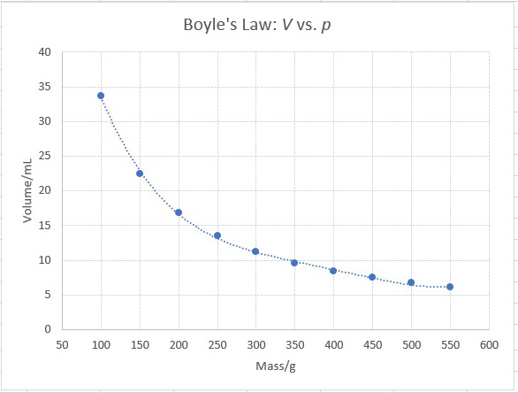
. As shown in the diagram PA PB 600 Nm2. These diagrams are showing. The various processes seen above can be combined to create cycles found in most internal and external combustion engines.
One mole of an ideal gas is initially at pressure P 1 volume V 1 and temperature T 1 represented by point A on the PV diagram. The vapor pressure P 2 of a pure liquid at a given temperature T is the pressure exerted by its vapor in equilibrium with the liquid phase in a closed system. The cycle consists of the following four processes.
The diagram below of pressure P versus volume V shows the expansion of 20 moles of a monatomic ideal gas from state A to state B. Pressure is force in newtons N divided by the area in square meters m 2 over which it acts P FA. A At P on the diagram above the pressure in the left ventricle is increasing.
2004Bb2 15 points The experimental diving bell shown above is lowered from rest at the oceans surface and reaches a maximum depth of 80 m. The pressure at A. The diagram below shows pressure and blood flow during the cardiac cycle in a dog.
Which particle diagram shown above best represents the strongest intermolecular force between two ethanol C2H6O molecules. Pressure and Volume. 83 is a pressure-composition p-x-y phase diagram that shows typical vaporliquid phase behavior for a binary system at a fixed temperature below the critical.
As shown in the above figure the Pxy diagram is a graph in which the pressure P is plotted on the vertical axis and the liquid phase composition x and gas phase composition y. All liquids and solids exist in. Volume is the amount of space is taken up by.
The pressure is then reduced to 200 Nm 2. 12 points suggested time 25 minutes The diagram above of pressure P versus volume V shows the contraction of 20 moles of a monatomic ideal gas from state A to state B. Click the card to flip.
Initially it accelerates downward at a rate of. As shown in the. At this time the rate of.
The diagram above of pressure P versus volume V shows the expansion of 20 moles of a monatomc ideal gas from state A to state B.

The Steam Engine And Other Heat Motors Tihsze Mal Loss In The Steam Turbine Ex 93 Compare The Theoretical Efficiency Of A Steam Engine Andthat Of A Steam Turbine Both Taking Steam At 150 Pounds Pressure The
Introduction Concepts Equilibrium Thermodynamics

Pxy Diagram Relationship Diagram Of Pressure Liquid And Gas Phases Chemical Engineering Reviewer
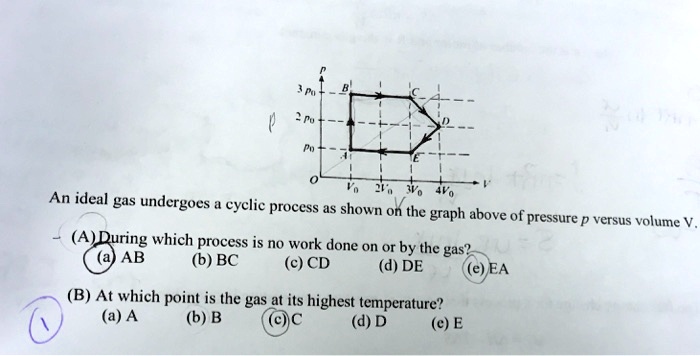
Solved An Ideal Gas Undergoes Cyclic Process As Shown On The Graph Above Of Pressure Versus Volume A During Which Process Is No Work Done On Or By The Ab Gas B Bc

Total Dy Vapour Pressure P Dy In Dependence On The Salt Temperature T S Download Scientific Diagram
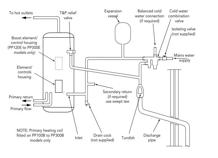
Solving Mixer Shower Problem My Blog
Ap Questions And Answers Ap Physics B
How To Calculate The Values Of Critical Pressure And Temperature For A Given Gas Van Der Waals Equation Quora

Petrographic And Geochemical Controls On Methane Genesis Pore Fractal Attributes And Sorption Of Lower Gondwana Coal Of Jharia Basin India Acs Omega

Phase Diagram Wikipedia
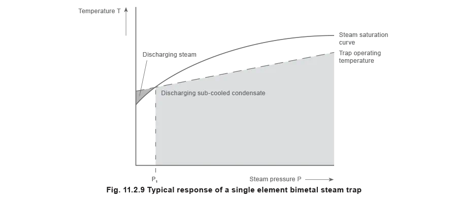
Thermostatic Steam Traps Spirax Sarco
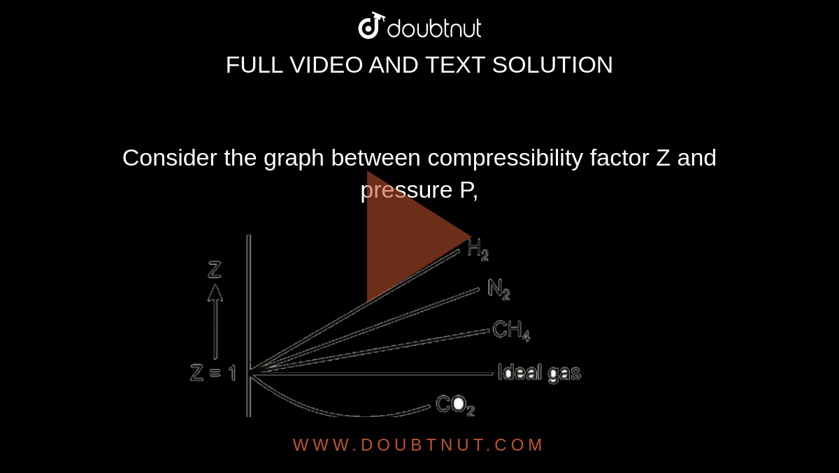
Consider The Graph Between Compressibility Factor Z And Pressure P The Correct Increasing Order Of Ease Of Liquefaction Of The Gases Shown In The Above Graph Is
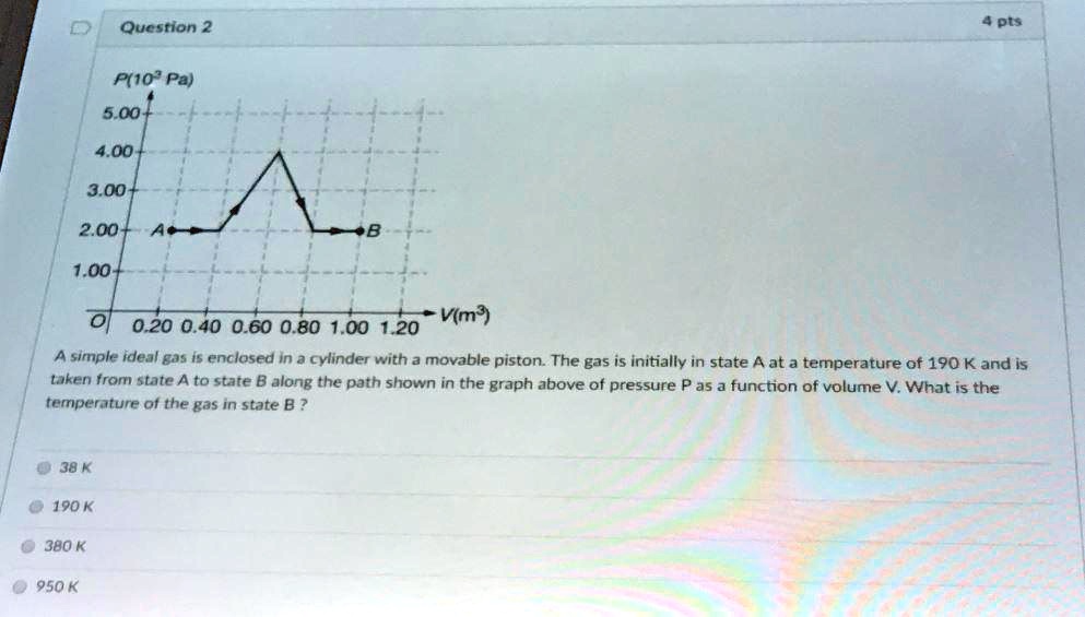
Solved Question 2 4pls P 1o Pa 5 00 4 00 3 00 2 00 1 00 V M 0 20 0 40 0 60 0 80 1 00 1 20 A Simple Ideal Ga5 Is Enclosed In 3 Cxlinder With A Movable Piston

Pressure Buildup An Overview Sciencedirect Topics
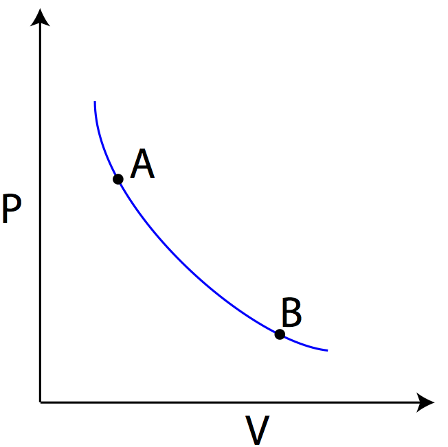
Ideal Gas Law
Pv Diagram Help Physics Forums
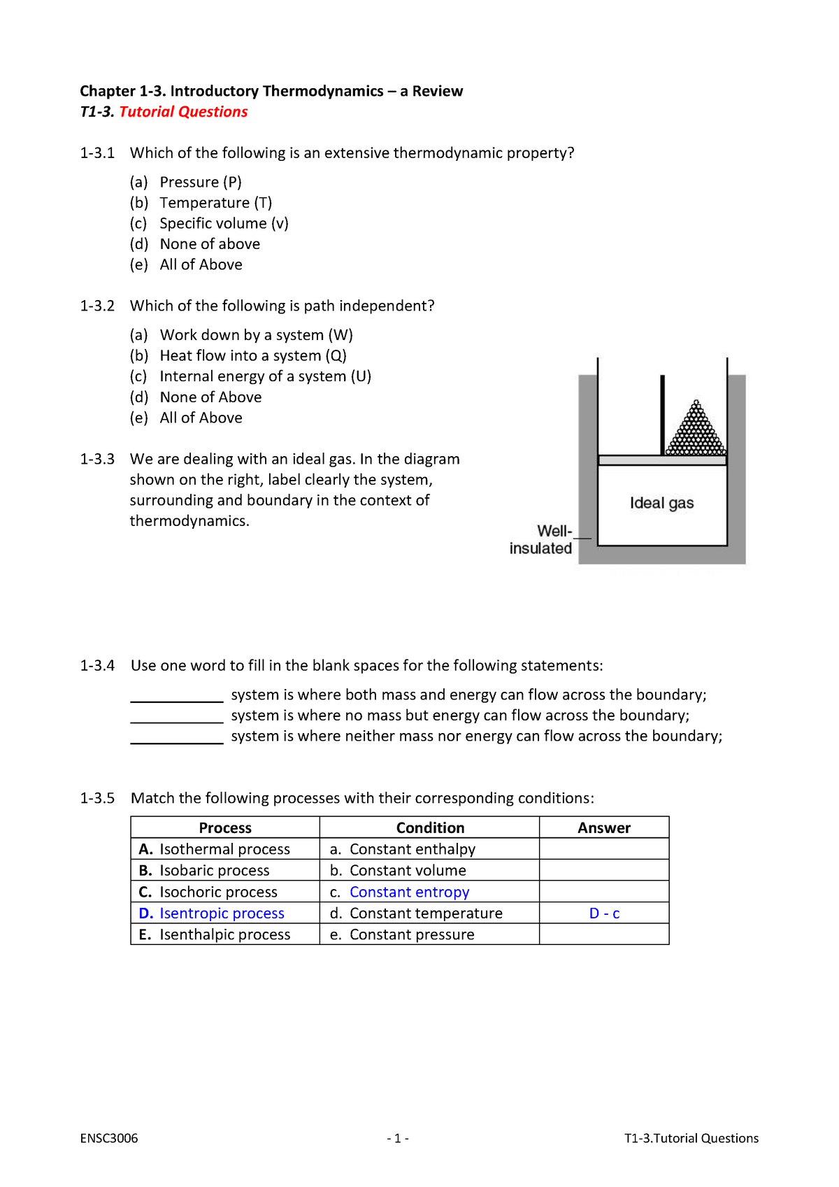
T1 3 Tutorial Questions Ensc3006 Uwa Studocu